Encapsulations
• PVC Frame Relay, MLFR, ATM, Dot1Q, QinQ, HDLC, PPP, MLPPP
Leased lines
Typically, these are referred to as a point-to-point connection or dedicated connection. A leased line is a pre-established WAN communications path from the CPE, through the DCE switch, to the CPE of the remote site, allowing DTE networks to communicate at any time with no setup procedures before transmitting data. When cost is no object, it’s really the best choice.HDLC and PPP encapsulations are frequently used on leased lines.
High-Level Data-Link Control
(HDLC) Protocol
(HDLC) Protocol
• The High-Level Data-Link Control (HDLC) protocol is a popular ISO-standard, bit-oriented Data Link layer protocol.
• HDLC is a point-to-point protocol used on
leased lines. No authentication can be used with HDLC.
• HDLC is the default encapsulation used by Cisco routers over synchronous serial links.
• Cisco’s HDLC is proprietary—it won’t communicate with any other vendor’s HDLC implementation.
HDLC
The reason that every vendor has a proprietary HDLC encapsulation method is that each vendor has a different way for the HDLC protocol to encapsulate multiple Network layer protocols. If the vendors didn’t have a way for HDLC to communicate the different layer 3 protocols, then HDLC would only be able to carry one protocol. This proprietary header is placed in the data field of the HDLC encapsulation.
PPP
• Since HDLC is the default serial encapsulation on Cisco serial links and it works great, when would you choose to use PPP? The basic purpose of PPP is to transport layer 3 packets across a Data Link layer point-to-point link. It is non-proprietary, which means that if you don’t have all Cisco routers, PPP would be needed on your serial interfaces—the HDLC encapsulation would not work because it is Cisco proprietary. In addition, PPP can encapsulate several layer 3 routed protocols.
PPP


FR
• Packet switching
This is a WAN switching method that allows you to share bandwidth with other companies to save money. Packet switching can be thought of as a network that’s designed to look like a leased line, yet charges you (and costs) more like circuit switching. There is a downside: If you need to transfer data constantly, forget about this option. Frame Relay provides a packet-switched network to many different customers at the same time
• Access rate The maximum speed at which the Frame Relay interface can transmit.
• CIR The maximum bandwidth of data guaranteed to be delivered. However, in reality, this is the average amount that the service provider will allow you to transmit.
Frame Relay operates using virtual circuits, as opposed to real circuits that leased lines use. Frame Relay PVCs are identified to DTE end devices using Data Link Connection Identifiers (DLCIs). A Frame Relay service provider typically assigns DLCI values, which are used on Frame Relay interfaces to distinguish between different virtual circuits

Local Management Interface (LMI) is a signaling standard used between your router and the first Frame Relay switch it’s connected to. It allows for passing information about the operation and status of the virtual circuit between the provider’s network and the DTE (your router).
interface Serial0
no ip address (notice there is no IP address on the interface!)
no ip directed-broadcast
encapsulation frame-relay
!
interface Serial0.102 point-to-point
ip address 10.1.12.1 255.255.255.0
no ip directed-broadcast
frame-relay interface-dlci 102
!
FR Frame Format

ATM
• ATM uses a fixed-length cell of 53 bytes.
The concept is that small cells introduce less delay. Devices waiting to transmit do not have to wait as long if cells are short. Smart cells can be processed more quickly than large cells, reducing the processing at network nodes. The small cell size was a compromise between the telephone and cable industries and the data industry. While large cell sizes are better for data, small cells work better for voice and video
• In ATM, a specified number of cells are made available during a time period. A device can take any available cell to transmit data (or multiple cells, as is typically the case). The ATM multiplexer takes the data received from the device, adds the 5-byte header, and transmits a cell. In some cases, the data may have to first be processed by the AAL, which then adds a header and trailer and passes the frame to the SAR, which then segments the data into several data units. The data units are then sent to ATM, where the header is added. ATM addressing consists of two identifiers which identify the virtual path and the virtual connection.
ATM Header
There are two formats for the ATM header. One header is used for the UNI, while the other is used for the NNI. The difference lies in the Generic Flow Control (GFC) parameter found in the UNI header. The GFC is not supported in the public network, nor was it intended to be.

• Following the VPI and the VCI is the Payload Type Indicator (PTI). This parameter indicates the type of data found in the payload portion of the cell. Remember that the payload is not always data. There could be signaling information, network management messages, and other forms of data. These are identified by the PTI.
• The PTI is followed by the Cell Loss Priority (CLP) parameter. This is used to prioritize cells. In the event of congestion or some other trouble, a node can discard cells that have a CLP value of 1 (considered low priority). If the CLP value is 0, the cell has a high priority and should only be discarded if it cannot be delivered.
• The last byte in the header is the Header Error Control (HEC) parameter, which is used for error checking and cell delineation. Only the header is checked for errors. The HEC works like other error checking methods, where an algorithm is run on the header and the value placed in the HEC. ATM is capable of fixing single bit errors but not multiple bit errors.
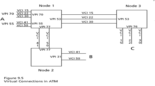
ATM addressing consists of two identifiers which identify the virtual path and the virtual connection.
• The UNI supports a maximum of 256 VPIs at any one node for each physical link. Remember that each VPI is an ATM link connection, with multiple virtual channels. A maxium of 64,000 virtual channels are supported for each virtual path. The NNI supports a maximum of 4096 VPIs because the NNI ATM header does not have the GFC parameter. Instead, these 4 bits are used to expand the VPI.
MLPPP

• MP is an optional feature of PPP, so it must be designed to integrate seamlessly into regular PPP operation. To accomplish this, MP is implemented as a new architectural “sublayer” within PPP. In essence, an MP sublayer is inserted as shown in the figure.
• Before MP can be used, a successful negotiation of at least the Multilink Maximum Received Reconstructed Unit option must be performed on each of the links between the two devices. Once this is done and an LCP link exists for each of the physical links, a virtual bundle is made of the LCP links and MP is enabled.
Transmission: MP accepts datagrams received from any of the network layer protocols configured using appropriate NCPs. It first encapsulates them into a modified version of the regular PPP frame. It then takes that frame and decides how to transmit it over the multiple physical links. Typically, this is done by dividing the frame into fragments that are evenly spread out over the set of links. These are then encapsulated and sent over the physical links. However, an alternate strategy can also be implemented as well, such as alternating full-sized frames between the links. Also, smaller frames are typically not fragmented, nor are control frames such as those used for link configuration.
Reception: MP takes the fragments received from all physical links and reassembles them into the original PPP frame. That frame is then processed like any PPP frame, by looking at its Protocol field and passing it to the appropriate network layer protocol.
Reception: MP takes the fragments received from all physical links and reassembles them into the original PPP frame. That frame is then processed like any PPP frame, by looking at its Protocol field and passing it to the appropriate network layer protocol.
MLFR
• The Multilink Frame Relay feature enables you to create a virtual interface called a bundle or bundle interface. The bundle interface serves as the Frame Relay data link and performs the same functions as a physical interface.
• The bundle is made up of physical serial links, called bundle links. The bundle links within a bundle function as one physical link. Bundle links are invisible to the Frame Relay data-link layer so Frame Relay functionality cannot be configured on these interfaces. Functionality that you want to apply to these links must be configured on the bundle interface. Bundle links are visible to peer devices. The local router and peer devices exchange link integrity protocol control messages to determine which bundle links are operational and to synchronize which bundle links should be associated with which bundles.
Dot1Q and QinQ
• Dot1Q is the encap type for any ethernet interface.
• Encapsulating IEEE 802.1Q VLAN tags within 802.1Q enables service providers to use a single VLAN to support customers who have multiple VLANs. The QinQ Support feature on the subinterface level preserves VLAN IDs and keeps traffic in different customer VLANs segregated. QinQ Support simply adds another layer of IEEE 802.1Q tag (called "metro tag" or "PE-VLAN") to the 802.1Q tagged packets that enter the network. The purpose is to expand the VLAN space by tagging the tagged packets, thus producing a "double-tagged" frame. The expanded VLAN space allows the service provider to provide certain services, such as Internet access on specific VLANs for specific customers, and yet still allows the service provider to provide other types of services for their other customers on other VLANs.
• Generally, the service provider's customers require a range of VLANs to handle multiple applications. Service providers can allow their customers to use this feature to safely assign their own VLAN IDs on subinterfaces because these subinterface VLAN IDs are encapsulated within a service provider-designated VLAN ID for that customer. Therefore there is no overlap of VLAN IDs among customers, nor does traffic from different customers become mixed. The double-tagged frame is "terminated" or assigned on a subinterface with an expanded encapsulation dot1q command that specifies the two VLAN ID tags (outer VLAN ID and inner VLAN ID) terminated on the subinterface.
QinQ

No comments:
Post a Comment