
AH (Authentication Header) is one of the two main components of the IPsec (Internet Protocol Security) protocol suite, along with the ESP (Encapsulating Security Payload). AH provides integrity and authentication services for IP packets, ensuring that they have not been tampered with or altered during transmission. Here's an overview of AH in IPsec:
1. **Integrity and Authentication**:
- AH provides integrity protection by calculating a cryptographic hash (usually using HMAC-SHA1 or HMAC-SHA256) over the entire IP packet (including the IP header and payload) and including the hash value in the AH header.
- The hash value is generated using a shared secret key known to both the sender and receiver. This allows the receiver to verify the integrity of the packet by recalculating the hash value and comparing it to the value included in the AH header.
2. **No Confidentiality**:
- Unlike ESP, which provides both integrity and confidentiality services, AH only provides integrity and authentication. It does not encrypt the packet payload, so the original payload is visible to anyone who intercepts the packet.
3. **AH Header Format**:
- The AH header is inserted between the IP header and the packet payload. It includes fields such as:
- Next Header: Specifies the type of the next header after the AH header (e.g., TCP, UDP).
- Payload Length: Specifies the length of the AH header and the payload.
- Security Parameters Index (SPI): A unique identifier that associates the packet with a particular security association.
- Sequence Number: An optional field used to prevent replay attacks by ensuring that packets are received in the correct order.
- Authentication Data (Hash): The computed hash value over the entire IP packet.
4. **Transport and Tunnel Mode**:
- AH can operate in either transport mode or tunnel mode, depending on the requirements of the IPsec deployment.
- In transport mode, AH protects the payload of the IP packet while leaving the IP header unchanged.
- In tunnel mode, AH protects both the IP header and payload of the packet. The entire original IP packet is encapsulated within a new IP packet with a new IP header.
5. **Compatibility and Limitations**:
- AH may encounter compatibility issues with certain network devices and NAT (Network Address Translation) configurations, as the IP addresses and certain fields in the IP header are protected by AH and cannot be modified without breaking the integrity check.
- AH cannot be used in scenarios where NAT is involved or when there is a need for confidentiality in addition to integrity and authentication.
In summary, AH in IPsec provides integrity and authentication services for IP packets, ensuring that they have not been tampered with during transmission. However, it does not provide confidentiality, and it may encounter compatibility issues in certain network configurations.
ESP (Encapsulating Security Payload) is one of the two main components of the IPsec (Internet Protocol Security) protocol suite, along with the Authentication Header (AH). ESP provides confidentiality, integrity, and authentication services for IP packets, making it a versatile and widely used protocol for securing communications over IP networks. Here's an overview of ESP in IPsec:
1. **Confidentiality**:
- One of the primary functions of ESP is to provide confidentiality by encrypting the payload (or inner IP packet) of the IP packet. This ensures that the contents of the packet are protected from eavesdropping or interception by unauthorized parties.
- ESP achieves confidentiality through encryption algorithms such as AES (Advanced Encryption Standard), DES (Data Encryption Standard), or 3DES (Triple DES). The choice of encryption algorithm depends on the security requirements of the IPsec deployment.
2. **Integrity and Authentication**:
- In addition to confidentiality, ESP also provides integrity and authentication services to ensure that the packet has not been tampered with during transmission.
- ESP calculates a cryptographic hash (similar to AH) over the entire IP packet (including the ESP header, payload, and optional padding), and includes the hash value in the ESP header. This allows the receiver to verify the integrity of the packet by recalculating the hash value and comparing it to the value included in the ESP header.
3. **ESP Header Format**:
- The ESP header is inserted between the IP header and the packet payload. It includes fields such as:
- Security Parameters Index (SPI): A unique identifier that associates the packet with a particular security association.
- Sequence Number: An optional field used to prevent replay attacks by ensuring that packets are received in the correct order.
- Payload Data: The encrypted payload of the IP packet.
- Authentication Data (Hash): The computed hash value over the entire IP packet.
4. **Transport and Tunnel Mode**:
- Similar to AH, ESP can operate in either transport mode or tunnel mode.
- In transport mode, ESP protects the payload of the IP packet while leaving the IP header unchanged.
- In tunnel mode, ESP protects both the IP header and payload of the packet. The entire original IP packet is encapsulated within a new IP packet with a new IP header.
5. **Compatibility and Interoperability**:
- ESP is widely supported by network devices and is interoperable with most IPsec implementations.
- It can be used in conjunction with AH for enhanced security or individually based on the specific security requirements of the deployment.
In summary, ESP in IPsec provides confidentiality, integrity, and authentication services for IP packets, making it a powerful tool for securing communications over IP networks. It encrypts the payload of the IP packet to ensure confidentiality, and calculates a cryptographic hash over the entire packet to ensure integrity and authentication.

VLAN (Virtual Local Area Network) tagging is a technique used in computer networking to allow multiple VLANs to coexist on the same physical network infrastructure, such as Ethernet. VLAN tagging involves adding an additional header to Ethernet frames to identify which VLAN the frame belongs to. This allows network switches to differentiate between traffic from different VLANs and appropriately forward the frames to their destination VLANs.
The VLAN tagging header consists of two main components:
1. **VLAN Tag**: This is a 4-byte header inserted into the Ethernet frame between the source MAC address and the EtherType/length field. The VLAN tag contains the following fields:
- **Priority**: 3 bits used to define the priority level of the frame (0-7). This is often referred to as the Quality of Service (QoS) priority.
- **C (Canonical Format Identifier)**: 1 bit used to indicate whether the VLAN ID field is in canonical format (0) or non-canonical format (1). This bit is used to ensure interoperability between different network devices.
- **VLAN ID (VID)**: 12 bits used to specify the VLAN to which the frame belongs. This field allows for up to 4096 unique VLANs (0-4095), although the actual number of usable VLANs may be lower depending on the specific networking equipment and configurations.
2. **EtherType/Length**: This field follows the VLAN tag and indicates the type of the payload data or the length of the frame. For VLAN-tagged frames, the EtherType field is set to a specific value (0x8100) known as the VLAN EtherType, indicating the presence of a VLAN tag.
When a network device receives a VLAN-tagged frame, it examines the VLAN tag to determine the appropriate VLAN for the frame. The device then forwards the frame only to ports associated with that VLAN, ensuring that the frame is delivered only to devices within the same VLAN. This segmentation helps to improve network security, reduce broadcast traffic, and facilitate network management.
VLAN tagging is commonly used in enterprise networks, data centers, and service provider networks to segment network traffic, isolate broadcast domains, and facilitate network management and troubleshooting. It is an essential feature of modern Ethernet networks and is supported by most managed switches and network devices.

The TCP (Transmission Control Protocol) header is a fundamental component of the TCP/IP protocol suite, which governs communication between devices over the Internet. It resides in the Transport Layer of the TCP/IP model and provides reliable, connection-oriented communication between hosts. The TCP header consists of various fields, each serving a specific purpose in managing the transmission of data. Here's an explanation of the key fields found in a TCP header:
1. **Source Port (16 bits)**:
- This field identifies the source port number of the sending device. Port numbers range from 0 to 65535 and help to differentiate multiple connections on the same host.
2. **Destination Port (16 bits)**:
- This field identifies the destination port number on the receiving device. Similar to the source port, it helps the receiving device identify the application or service to which the segment is destined.
3. **Sequence Number (32 bits)**:
- The sequence number field specifies the sequence number of the first data byte in the TCP segment. It is used for ordering and reassembling received segments at the receiving end.
4. **Acknowledgment Number (32 bits)**:
- In TCP, acknowledgments (ACKs) are used to confirm receipt of data segments. This field contains the sequence number that the receiver expects to receive next. It acknowledges the receipt of all previous bytes.
5. **Data Offset (4 bits)**:
- This field indicates the length of the TCP header in 32-bit words. Since the TCP header size can vary (due to options), this field is used to determine the start of the data payload.
6. **Reserved (3 bits)**:
- These bits are reserved for future use and are set to zero in the current specification of TCP.
7. **Flags (9 bits)**:
- TCP uses various control flags to manage the connection state and control the behavior of data transmission. These flags include:
- **URG (Urgent Pointer)**: Indicates that the Urgent pointer field is significant.
- **ACK (Acknowledgment)**: Indicates that the Acknowledgment field is significant.
- **PSH (Push)**: Push function. Asks to push the buffered data to the receiving application.
- **RST (Reset)**: Reset the connection.
- **SYN (Synchronize)**: Synchronize sequence numbers. Used to initiate a connection.
- **FIN (Finish)**: No more data from sender. Used to terminate a connection.
8. **Window Size (16 bits)**:
- This field specifies the size of the receive window, which indicates the number of bytes that the sender can transmit before receiving an acknowledgment. It helps in flow control, allowing the sender to regulate the rate of data transmission.
9. **Checksum (16 bits)**:
- The TCP checksum field is used to detect errors in the TCP segment during transmission. It is computed over the TCP header, data payload, and pseudo-header (including source and destination IP addresses) and helps ensure the integrity of the transmitted data.
10. **Urgent Pointer (16 bits)**:
- If the URG flag is set, this field indicates the byte offset from the current sequence number where urgent data ends.
11. **Options**:
- The TCP header may contain optional fields or options, which are used for various purposes such as timestamping, selective acknowledgment (SACK), window scaling, and maximum segment size (MSS).
The TCP header, along with the TCP segment payload, forms the TCP segment, which is encapsulated within an IP packet and transmitted over the network. By providing reliable, connection-oriented communication, TCP ensures that data is delivered accurately and in order between hosts on a network.
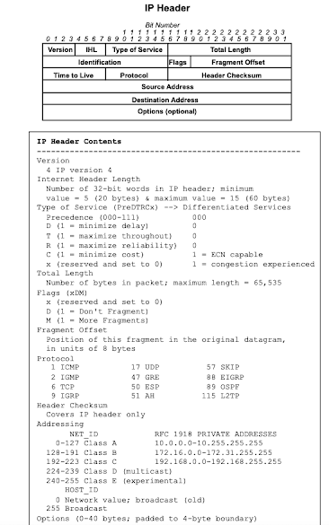
The IP (Internet Protocol) header is a crucial component of the TCP/IP protocol suite, responsible for routing data packets across networks. It resides in the Network Layer of the TCP/IP model and provides a set of essential fields that govern the delivery of packets from a source to a destination. Here's an explanation of the key fields found in an IPv4 header:
1. **Version (4 bits)**:
- This field indicates the version of the IP protocol being used. For IPv4, the value is 4.
2. **Header Length (4 bits)**:
- The header length field specifies the length of the IP header in 32-bit words. Since the IPv4 header size can vary (due to options), this field is used to determine the start of the data payload.
3. **Type of Service (8 bits)**:
- The Type of Service (TOS) field is used to specify the quality of service (QoS) level for the packet. It includes subfields such as Precedence, Delay, Throughput, Reliability, and Cost.
4. **Total Length (16 bits)**:
- This field specifies the total length of the IP packet, including the header and data payload. It ranges from 20 to 65,535 bytes.
5. **Identification (16 bits)**:
- The identification field is used for fragmentation and reassembly of IP packets. It helps to uniquely identify fragments belonging to the same original packet.
6. **Flags (3 bits)**:
- The Flags field contains control flags used for fragmentation. The three flags are:
- **Reserved (Bit 0)**: Reserved for future use and must be set to 0.
- **Don't Fragment (DF) (Bit 1)**: If set, indicates that the packet should not be fragmented.
- **More Fragments (MF) (Bit 2)**: If set, indicates that more fragments follow the current fragment.
7. **Fragment Offset (13 bits)**:
- This field indicates the offset of the current fragment relative to the beginning of the original packet. It is used in conjunction with the Identification field for reassembly.
8. **Time to Live (TTL) (8 bits)**:
- The TTL field specifies the maximum number of hops (routers) that the packet can traverse before being discarded. Each router decrements the TTL value by at least one, and if it reaches zero, the packet is discarded.
9. **Protocol (8 bits)**:
- This field identifies the protocol used in the data payload of the IP packet (e.g., TCP, UDP, ICMP). It helps the receiving device determine how to process the packet payload.
10. **Header Checksum (16 bits)**:
- The header checksum field is used to detect errors in the IP header during transmission. It is computed over the IP header and helps ensure the integrity of the transmitted packet.
11. **Source IP Address (32 bits)**:
- This field specifies the source IP address of the sending device, identifying the originator of the packet.
12. **Destination IP Address (32 bits)**:
- This field specifies the destination IP address of the receiving device, identifying the intended recipient of the packet.
The IP header, along with the data payload, forms the IP packet, which is encapsulated within a data link layer frame (e.g., Ethernet frame) and transmitted over the network. By providing a set of essential fields for routing and delivery, the IP header ensures that data packets are properly routed across interconnected networks.

PING (Packet Internet Groper) is a utility used to test the reachability of a host on an Internet Protocol (IP) network and to measure the round-trip time (RTT) for packets sent from the originating host to a destination computer. The PING utility works by sending ICMP Echo Request packets to the target host and waiting for ICMP Echo Reply packets in response.
While PING itself doesn't have a "header" in the traditional sense like TCP or IP packets, ICMP (Internet Control Message Protocol) packets, including the Echo Request and Echo Reply packets used by PING, do have headers. Here's an explanation of the key fields found in an ICMP Echo Request and Echo Reply packet:
1. **Type (8 bits)**:
- The Type field specifies the type of ICMP message. For PING, the Type is set to 8 for Echo Request packets and 0 for Echo Reply packets.
2. **Code (8 bits)**:
- The Code field provides additional information or context for the ICMP message. For PING, the Code is typically set to 0.
3. **Checksum (16 bits)**:
- The Checksum field is used to detect errors in the ICMP message during transmission. It is computed over the entire ICMP packet, including the header and data payload, and helps ensure the integrity of the transmitted packet.
4. **Identifier (16 bits)**:
- The Identifier field is used to identify the PING process sending the Echo Request packet. It allows the sender to match Echo Reply packets to the corresponding Echo Request packets.
5. **Sequence Number (16 bits)**:
- The Sequence Number field is incremented for each Echo Request packet sent by the PING process. It allows the sender to identify and match Echo Reply packets to the corresponding Echo Request packets.
6. **Data (Variable length)**:
- The Data field contains optional data sent by the sender in the Echo Request packet. This data is typically used for diagnostic purposes or to measure network performance.
When the destination host receives an ICMP Echo Request packet, it responds with an ICMP Echo Reply packet. The Echo Reply packet contains the same Identifier and Sequence Number as the corresponding Echo Request packet, allowing the sender to match the reply to the original request.
In summary, while PING itself doesn't have a header, the ICMP packets used by PING do have headers that contain essential fields such as Type, Code, Checksum, Identifier, Sequence Number, and optional Data. These fields help facilitate communication between the PING sender and the destination host, allowing for network testing and troubleshooting.

ICMP (Internet Control Message Protocol) is a network layer protocol used to send control messages and error reporting between network devices in an IP network. ICMP messages are encapsulated within IP packets and are used for various purposes, including network diagnostics, error reporting, and management. The ICMP header consists of several fields that are used to convey information between network devices. Here's an explanation of the key fields found in an ICMP header:
1. **Type (8 bits)**:
- The Type field specifies the type of ICMP message. It indicates the purpose or function of the ICMP packet. Common types of ICMP messages include:
- **Echo Request (Type 8)**: Used by the PING utility to test reachability and measure round-trip time to a destination.
- **Echo Reply (Type 0)**: Sent in response to an Echo Request message, confirming that the destination is reachable and providing round-trip time information.
- **Destination Unreachable (Type 3)**: Indicates that the destination host or network is unreachable.
- **Time Exceeded (Type 11)**: Indicates that the Time to Live (TTL) field of an IP packet has expired.
- **Parameter Problem (Type 12)**: Indicates that there is an issue with one or more parameters in the IP header.
- **Redirect (Type 5)**: Informs a host about a better route to a particular destination.
2. **Code (8 bits)**:
- The Code field provides additional information or context for the ICMP message. It further specifies the type of ICMP message. For example, for an ICMP Destination Unreachable message, the Code field might indicate the reason for the unreachable condition (e.g., network unreachable, host unreachable).
3. **Checksum (16 bits)**:
- The Checksum field is used to detect errors in the ICMP message during transmission. It is computed over the entire ICMP packet, including the header and data payload, and helps ensure the integrity of the transmitted packet.
4. **Data (Variable length)**:
- The Data field contains optional data specific to the type and code of the ICMP message. The content of this field varies depending on the purpose of the ICMP message. For example, in an Echo Request message, the Data field may contain arbitrary data used for testing, while in a Destination Unreachable message, it may include an encapsulated IP header and a portion of the original packet that triggered the error.
The ICMP header is encapsulated within an IP packet, and ICMP messages are typically transmitted as IP datagrams over an IP network. ICMP plays a critical role in network troubleshooting and management by providing feedback about the status of network connections and assisting in diagnosing network-related issues.

The DNS (Domain Name System) protocol is responsible for translating domain names (e.g., www.example.com) into IP addresses (e.g., 192.0.2.1) and vice versa. The DNS operates through a client-server model, where DNS clients (such as web browsers or other applications) send DNS queries to DNS servers to resolve domain names to IP addresses.
The DNS header is a fundamental component of DNS messages and contains essential information about the DNS query or response. Here's an explanation of the key fields found in a DNS header:
1. **Transaction ID (16 bits)**:
- The Transaction ID field uniquely identifies the DNS query and its corresponding response. It allows the DNS client to match responses with the original queries.
2. **Flags (16 bits)**:
- The Flags field contains various control flags that specify the type of DNS message (query or response), query type, response code, and other parameters. Some important flags include:
- **QR (Query/Response)**: Indicates whether the message is a query (0) or a response (1).
- **Opcode**: Specifies the type of query (e.g., standard query, inverse query, status request).
- **AA (Authoritative Answer)**: Indicates whether the responding DNS server is authoritative for the queried domain.
- **TC (Truncated)**: Indicates that the DNS message was truncated due to being too large to fit in a single UDP packet.
- **RD (Recursion Desired)**: Indicates whether the client requests recursive resolution from the DNS server.
- **RA (Recursion Available)**: Indicates whether the DNS server supports recursive resolution.
- **RCODE (Response Code)**: Specifies the result of the DNS query (e.g., no error, name error, server failure).
3. **Question Count (16 bits)**:
- The Question Count field specifies the number of entries in the question section of the DNS message. Each entry represents a domain name that the client is querying.
4. **Answer Record Count (16 bits)**:
- The Answer Record Count field specifies the number of resource records in the answer section of the DNS response. Each resource record contains information mapping domain names to IP addresses.
5. **Authority Record Count (16 bits)**:
- The Authority Record Count field specifies the number of resource records in the authority section of the DNS response. Authority records provide information about the authoritative DNS servers for the queried domain.
6. **Additional Record Count (16 bits)**:
- The Additional Record Count field specifies the number of additional resource records in the additional section of the DNS response. Additional records may include additional information relevant to the query, such as DNS server addresses or DNSSEC signatures.
The DNS header is followed by the question section, which contains the domain names being queried, and optional answer, authority, and additional sections containing resource records with DNS resolution information.
Overall, the DNS header contains critical metadata about DNS queries and responses, enabling efficient communication between DNS clients and servers and facilitating the resolution of domain names to IP addresses.

The ARP (Address Resolution Protocol) is a communication protocol used to map IP addresses to MAC addresses within a local network segment. It helps devices on the same network determine each other's hardware (MAC) addresses when only their IP addresses are known. ARP operates at the data link layer (Layer 2) of the OSI model.
The ARP protocol doesn't have a distinct header like some other protocols (e.g., TCP, UDP), but rather its fields are embedded within an Ethernet frame. When an ARP message is sent, it is encapsulated within an Ethernet frame, and the ARP information is contained within the payload of the Ethernet frame.
Here's an explanation of the key fields found in an ARP message:
1. **Hardware Type (2 bytes)**:
- Specifies the type of hardware (e.g., Ethernet) being used on the network. Common values include 1 for Ethernet.
2. **Protocol Type (2 bytes)**:
- Indicates the protocol type being used (e.g., IPv4). Common values include 0x0800 for IPv4.
3. **Hardware Address Length (1 byte)**:
- Specifies the length of hardware addresses (MAC addresses) in bytes. For Ethernet, this value is typically 6 bytes.
4. **Protocol Address Length (1 byte)**:
- Specifies the length of protocol addresses (IP addresses) in bytes. For IPv4, this value is typically 4 bytes.
5. **Operation (2 bytes)**:
- Indicates the type of ARP message being sent. Common values include:
- 1: ARP Request
- 2: ARP Reply
6. **Sender Hardware Address (variable length)**:
- Contains the MAC address of the sender of the ARP message.
7. **Sender Protocol Address (variable length)**:
- Contains the IP address of the sender of the ARP message.
8. **Target Hardware Address (variable length)**:
- In an ARP Request, this field is typically empty (all zeroes) since the sender is requesting the MAC address of another device. In an ARP Reply, it contains the MAC address of the target device.
9. **Target Protocol Address (variable length)**:
- Contains the IP address of the target device.
When a device needs to send data to another device on the same local network segment, it checks its ARP cache to see if it has the MAC address of the destination IP address. If not, it sends out an ARP Request message broadcasted to all devices on the local network asking, "Who has this IP address? Please tell me your MAC address." The device with the matching IP address then responds with an ARP Reply message containing its MAC address.
Overall, ARP plays a crucial role in enabling communication between devices on the same network by resolving IP addresses to MAC addresses, facilitating the transmission of data at the data link layer.

The UDP (User Datagram Protocol) header is a fundamental component of the UDP protocol, which operates at the transport layer (Layer 4) of the OSI model. UDP is a connectionless and unreliable protocol used for transmitting datagrams between hosts on an IP network. The UDP header contains information necessary for delivering UDP datagrams from the source to the destination.
Here's an explanation of the key fields found in a UDP header:
1. **Source Port (16 bits)**:
- This field specifies the source port number of the sending application or process. Port numbers range from 0 to 65535 and help identify the application or service sending the UDP datagram.
2. **Destination Port (16 bits)**:
- This field specifies the destination port number on the receiving host. Similar to the source port, it helps identify the application or service to which the UDP datagram is destined.
3. **Length (16 bits)**:
- The Length field specifies the length of the UDP datagram, including the header and data payload, in bytes. The minimum value for this field is 8 bytes (the size of the UDP header), and the maximum value is 65,535 bytes.
4. **Checksum (16 bits)**:
- The Checksum field is used to detect errors in the UDP datagram during transmission. It is optional in UDP, and if not used, the field is set to zero. When checksumming is enabled, the sender calculates a checksum over the entire UDP datagram (including the UDP header, pseudo-header, and data payload) and includes it in this field. The receiver recalculates the checksum and compares it to the value in the UDP header to verify the integrity of the datagram.
The UDP header is relatively simple compared to other transport layer protocols like TCP. It provides minimal functionality, focusing primarily on source and destination port identification and datagram length. UDP is widely used for applications that prioritize speed and efficiency over reliability, such as real-time multimedia streaming, DNS (Domain Name System), and DHCP (Dynamic Host Configuration Protocol). However, because UDP lacks features like error correction, flow control, and congestion control, applications built on UDP must implement their own mechanisms for handling these issues if necessary.
Ethernet

The Ethernet header is a fundamental component of Ethernet frames, which are used to encapsulate data for transmission over Ethernet networks. Ethernet operates at the data link layer (Layer 2) of the OSI model and provides a mechanism for delivering data between devices on the same local network segment. The Ethernet header contains essential information necessary for the transmission and reception of Ethernet frames.
Here's an explanation of the key fields found in an Ethernet header:
1. **Destination MAC Address (6 bytes)**:
- This field specifies the MAC (Media Access Control) address of the destination device to which the Ethernet frame is being sent. MAC addresses are unique identifiers assigned to network interfaces and are used for addressing and routing Ethernet frames within a local network.
2. **Source MAC Address (6 bytes)**:
- This field specifies the MAC address of the sending device that originates the Ethernet frame. It identifies the source of the frame and allows the recipient to send responses or acknowledgments back to the sender.
3. **EtherType or Length (2 bytes)**:
- The EtherType field specifies the type of the payload data encapsulated within the Ethernet frame. Common EtherType values include:
- **IPv4 (0x0800)**: Indicates that the payload data is an IPv4 packet.
- **IPv6 (0x86DD)**: Indicates that the payload data is an IPv6 packet.
- **ARP (0x0806)**: Indicates that the payload data is an ARP (Address Resolution Protocol) message.
- **VLAN Tagging (0x8100)**: Indicates the presence of VLAN tagging in the Ethernet frame.
Alternatively, when Ethernet II framing is used, this field is referred to as Length and specifies the length of the payload data in bytes.
4. **Optional VLAN Tag (4 bytes)**:
- If VLAN tagging is used, an additional 4-byte VLAN tag may be present in the Ethernet header. The VLAN tag contains information such as the VLAN identifier (VID) and priority level for the frame.
5. **Frame Check Sequence (FCS) (4 bytes)**:
- The FCS field contains a cyclic redundancy check (CRC) value computed over the entire Ethernet frame (excluding the preamble and start frame delimiter) to detect transmission errors. The receiving device calculates its own CRC value based on the received frame and compares it to the FCS value in the Ethernet frame to verify the integrity of the data.
The Ethernet header, along with the payload data and FCS, forms the Ethernet frame, which is transmitted over the physical network medium. By providing addressing, error detection, and EtherType information, the Ethernet header facilitates the reliable transmission of data between devices on an Ethernet network.


