Pages

Tuesday, August 26, 2014

Route Redistribution Notes

Route Redistribution Overview
=============================
Redistribution occurs from the routing table not the routing database
When redistributing protocol X into Y, take
-routes in the routing table via protocol X
-connected interfaces running protocol X

Route advertisement rules
-RIP vs EIGRP vs OSPF vs BGP

Connected Redistribution
=====================
Implicitly occurs for connected links running the redistributed protocol
Additional connected links can explicitly included or excluded
-redistribute connected [metric] ][route-map]
-overrides implicit redistribution

How IOS chooses Path
=======================
Routing database chooses one or more candidate paths
-EIGRP via DUAL, OSPF via SPF, etc
-Load-balancing possible via maximum-paths

IF multiple equal matches between protocols
-choose the lower AD

Install results in RIB and/or FIB

Administrative Distance Values
======================
0 : connected
1 : static
5 : EIGRP summary
20 : External BGP
90 : Interal EIGRP
110 : OSPF
115 : IS-IS
120 : RIP
160 : ODR
170 : External EIGRP
200 : Internal BGP
255 : Infinite

RIP Redistribution
=================
Doesn’t differentiate between internal and external routes
-AD of 120 for all routes
No default seed metric
-redistribute [protocol] metric [hops]
-default-metric [hops]

EIGRP redistribution
===================
AD of 170 for external EIGRP
-helps to automatically prevent route feedback
Uses router-id for loop prevention
No default seed metric unless EIGRP to EIGRP
-redistribute [protocol] metric [bw] [delay] [load] [relaibility] [mtu]
-default-metric [“”]

OSPF redistribution
==================
AD of 110 for all OSPF routes
Uses Router-ID for flooding loop prevention
Default seed metric 20 and metric-type E2/N2
OSpf path selection preference
-E1>E2>N1>N2
-E1 & N1 vs E2 & N2 metrics

BGP redistribution
=================
Uses ORIGIN code incomplete (?)
Normal EBGP and IBGP loop prevention
IGP to BGP
-denies ospf external by default
.redistribute ospf [pid] match internal external
BGP to IGP
-EBGP routes allowed, iBGP routes denied by default
.bgp redistribute-internal
.legacy synchronization rule

.can cause routing loop

OSPF Notes

OSPF Overview
==========
Classless link-state protocol
-uses Dijkstra SPF algorithm
-maintains active adjacencies
-supports VLSM
-supports both topology and NLRI summarization

Enabling OSPF
===============
Enable the global process
-router ospf [process-id]
.process-id is locally significant
-Must be an up/up interface running IP
.used for OSPF Router-ID
Enable the interface process
-network [address] [wildcard] area [area]
-ip ospf [process-id] area [area]

Verifying OSPF
===============
Verify OSPF is enabled
-show ip ospf
-show ip ospf interface [brief]
Verify OSPF adjacency's
-show ip ospf neighbor
-show ip ospf adj
Verify ospf database
-show ip ospf database [router | network | summary]

Neighbor and Topology Discovery
==========================
Like EIGRP, OSPF use hello packets to discover neighbors
-transport via IP protocol 89 (OSPF)
-sent as multicast to 224..0.0.5 or 224.0.0.6 or unicast
Hello packets contain attributes that neighbors must agree on to form adjacency
Once adjacency is negotiated, LSDB is exchanged.

Negotiating OSPF Adjacencies
========================
Neighbors must agree on attributes to form adjacency
-Not all ospf neighbors actually form adj
-most ospf configuration problems happen at this stage
Unique attributes include…
-local Router-id
-local interface ip address

Negotiating OSPF adjacencies
========================
Common attributes include…
-interface area-id
-hello interval and dead interval
-interface network address
-interface MTU
-network Type
-Authentication
-stub flags
-other optional capabilities

OSPF Media Dependencies
=======================
OSPF  behavior changes based on media
-eg Ethernet vs FR vs PPP
Different media uses different “network types “ to control..
-how updates are sent
-who forms adjacency
-how next-hop is calculated

OSPF Network Types
=================
Broadcast
Non-broadcast
Point-to-point
Point-to-multipoint
Point-to-multipoint nonbroadcast
Loopback

OSPF Network Broadcast
====================
Ip ospf network broadcast
Default on multi-access broadcast medias
-ethernet, token ring, & FDDI
Sends hellos and updates as multicast
-224.0.0.5 (AllSPFRouters)
-224.0.0.6 (All DR Routers)
Performs DR and BDR election

DR/BDR Overview
====================
Designated Router (DR)
-used on broadcast links to
.minimize adjacencies
.minimize LSA replication
Backup DR
-used for redundancy of DR
DROthers
-All other routers on link
-form full adjacency with DR & BDR
-stop at 2way adj with each other
DR/BDR choosen through election process

DR/BDR election
===================
Election based on the below field present in hello packets
-priority
0-255
Higher better
0 = never
-Router-id
.Highest loopback/interface Ip
.can be statically set
.higher better
.No preemption unlike IS-IS’s DIS

OSPF Network Non-Broadcast
======================
Ip ospf network non-broadcast
Default on multipoint NBMA medias
-FR & ATM
Sends hellos as unicast
-manually defined addresses with neighbor command
-performs DR/BDR election

OSPF Network Point-to-multipoint
==========================
Ip ospf network point-to-multipoint
Treats network as a collection of point-to-point links
Sends hellos as multicast
-224.0.0.5
No DR/BDR election
Special next-hop processing
Usually the best design option for partial mesh NBMA networks

OSPF network Point-to-point
======================
ip ospf network point-to-point
Default on point-to-point medias
-HDLC/PPP
Sends hellos as multicast
-224.0.0.5
No DR/BDR election
Supports only two neighbors on the link

Point to multipoint Non-broadcast
===========================
Ip ospf network point-to-multipoint non-broadcast
Same as point-to-multipoint, but sends hellos as unicast
-manually defined addresses with neighbor command
-allows for per-VC OSPF cost over NBMA
No DR/BDR election
Special next-hop processing

OSPF Network Loopback
===================
Special case for loopback and looped-back interfaces
Advertises link as /32 stub host route
Ip ospf network point-to-point (used to disable loopback)

OSPF PATH Selection
=================
Once databases are synchronized, path selection begins
Each router’s LSA include a “cost” attribute for each described link
Best path to that link is lowest end-to-end cost
Cisco’s implementation uses bandwidth based cost, but per RFC it is arbitrary
-default cisco cost = 100 Mbps/Link BW
-reference bandwidth can be modified to accommodate higher speed links (eg GigE)

OSPfF path selection order
============================
Per RFC, ospf path selection state machine prefers..
-Intra area routes (O)
-Inter area routes (O IA)
-External Type 1 (E1)
-External Type 2 (E2)
-NSSA Type 1 (N1)
-NSSA Type 2 (N2)
Cannot be modified with metric or distance.

Modifying OSPF path selection
=============================
Ospf uses bandwidth based cost
-COST = ref BW/Interface_BW
Cost can be modified with
-interface bandwidth
-interface ip ospf cost
-process auto-cost
-process neighbor [address] cost

OSPF convergence Timers
======================
Convergence based on hello and dead timer
-supports sub-second timers
Different timers for different network types
-show ip ospf interface
Changing hello time automatically adjusts dead time
-ip ospf hello-interval
-ip ospf dead-interval
Note: bidirectional forwarding detection is used for L2 link failures in ospf when we use switches in between routers.

OSPF Authentication
====================
OSPF supports 3 types of authentication
-0 = Null
-1 = clear test
-2 = MD5
Can be enabled
-on all links in the area (ie configured on a process)
-on a per link basis
Key is always applied at link level
-virtual-links are area 0 interfaces

OSPF Summarization
======================
All devices within the area must have the same LSDB
Implies summarization can only occur
-between areas
.area [source area] range [address] [mask]
-during redistribution
.summary-address [address] [mask]
Automatically generates discard route
-disabled with no discard route [internal | external]
Can be used for TE via longest match routing

OSPF Filtering Overview
====================
OSpf is a link-state routing protocol
-to calculate identical SPTs everyone must have the same input to SPF(the LSDB)
-Implies that filtering cannot be configured within an area
Inter-area filtering through
-stub areas
-LSA 3 filter

OSPF Stub Areas
=================
Stub areas used to limit type of LSAs allowed to enter an area
-Intra Area routes (O)
.LSA 1 & 2
Inter area routes (O IA)
.LSA 3 & 4
-External routes (E1 & E2)
.LSA 5
-NSSA external routes (N1 & N2)
.LSA 7

All routers in an area must agree on the stub flag

OSPF Stub Areas
===========
Stub Area
-removes external routes (LSA 5)
-removes ASBR advertisement (LSA 4)
-ABR originates inter-area default route (LSA 3)

Enabled on all routers in an area
-area [area id] stub

OSPF Stub Areas
============
Totally stub Area
-removes external routes (LSA 5)
-removes ASBR advertisement (LSA 4)
-removes inter-area routes (LSA 3)
-ABR orginates inter-area default route (LSA 3)

Stub enabled on all routers in the area
-area [area] stub

Totally stubby enabled on ABR(s) of the area
-area [area] stub no-summary

OSPF Stub Areas
=============
Not-so-stubby area (NSSA)
-allows NSSA external generation (LSA 7)
-removes external routes (LSA 5)
-removes ASBR advertisement (LSA 4)

All routers must agree on NSSA
-area [area] nssa

ABR does not originate default automatically
-can be configured to generate LSA 7 default
-area [area] nssa default-information-originate

OSPF stub Areas
===============
Not-so-totally-stubby area
-allows NSSA external generation (LSA 7)
-removes external routes (LSA 5)
-removes ASBR advertisement (LSA 4)
-removes inter-area routes (LSA 3)
-ABR originates inter-area default route (LSA 3)

NSSA enabled on all routers in the area
-area [area] nssa

Totally stubby enabled on ABR(s) of the area
-area [area] nssa no-summary

Controlling NSSA Redistribution
============================
Redistributed routes on an NSSA router are originated as LSA 7
If NSSA ASBR is also an ABR..
-type 7 originated into NSSA
-type 5 originated into Area 0

Type 7 origination can be suppressed
-area [area] nssa no-redistribution
-send type 5 to area 0 but not type 7 to NSSA

NSSA Translator Election
================
NSSA ABR translates Type 7 LSAs into Type 5 for Area 0 advertisement
If multiple ABRs, only on of them performs translation
-NSSA translator election chooses ABR with the higher router-id
IF forwarding address is non-zero, ABR need not be in the transit path

LSA 3 Filter
==============
Stub areas can only filter on LSA type
ABRs can filter which summary LSAs (LSA 3) they generate between areas
Applied to process level of ABR
-area [area] filter-list prefix [prefix-list] [in | out]

-In/out allows for control of ABRs with more than 2 areas

Tuesday, August 5, 2014

BGP Notes

BGP Overview
============
Open Standards based
-RFC 4271 “ A border gateway protocol 4 (BGP-4)”
Classless path vector routing protocol
-uses multiple “attributes” for routing decision
-supports VLSM and summarization
-Extensible
 IPV4 Multicast, IPv6, MPLS, etc.

BGP ASNs
=============
Autonomous Systems (AS)
-a set of routers under a single technical administration, using an interior gateway protocol(IGP) and common metrics to determine how to route packets within the AS, and using an inter-AS routing protocol to determine how to route packets to other Ases.
ASNs are allocated by Internet assigned number authority (IANA)
Generally, BGP relies on ospf, ISIS, Eigrp to advertise routing within AS.

BGP ASN Values
================
Originally 2 byte field
-value 0-65535
-public  ASNs 1-64511
-private ASNs 64512-65535

Now 2 byte is already occupied so we come up with 4 byte AS

Currently 4-byte field
-BGP support for four-octet AS number space

4-Byte BGP ASN
==============
0.0   – 65535.65535 notation
-0.[0-65535] denote original 2 byte ASNs
Requires backwards compatibility with old code.
-4 byte ASN support negotiated during capability exchange
-old bgp speakers are sent ASdot numbers encoded as ASN “23456”
-real AS-Path encoded with optional transitive  attributes AS4_AGGREGATOR and AS4_PATH

Establishing BGP Peerings
=====================
Like IGP, the first step in BGP is to find neighbors to exchange information with
Unlike IGP..
-BGP does not have its own transport
-BGP has different types of neighbors
-BGP neighbors are not discovered
-BGP neighbors do not have to be connected
Since we have a TCP used as a L4 protocol(logical) for the establishment, hence neighbors in case of IBGP need not to be directly connected.

BGP Transport
================
BGP uses TCP port 179 for transport
-Implies that BGP needs IGP first
BGP neighbor statements tells process to
-listen for remote address via TCP 179
-initiate a session to remote address via TCP 179
-If collision, higher router-id becomes TCP client
Note: if you want to use BGP only then there should be a physical connection between all routers ie full mesh which has again routing issues. Hence we use IGP within IBGP for route recursion process to BGP next hop value.

BGP Peering Types
===============
External BGP (EBGP ) peers
-neighbors outside my AS
Internal BGP(iBGP) Peers
-neighbors inside my AS
Update and pacth selection rules change depending on what type of peer a route is being sent to/received from

BGP Peering Rules
===========
EBGP packets default to TTL 1
-Can be modified if neighbors are multiple hops away
.neighbor ebgp-multihop [ttl]
.neighbor ttl-security hops [ttl]
Nom multi-hop peers must be directly connected by default
-can be modified if connected neighbors peer via Loopbacks
.neighbor disable –connected-check

Loop prevention via AS-PATH
-Local ASN is prepended to outbound updates
-Inbound updates containing local ASN are discarded
-can be modified with neighbor allows-in

Next-hop processing
-outbound EBGP updates have local update-source for neighbor set as next-hop
Eg. If update-source is Loopback0, next –hop is loopback0
-Can be modified with route-map action set ip next-hop but typically shouldn’t
.eg third-party next-hop

Note: control plane = session = routing update
Data plane = data forwarding = actual data flow.
IBGP packets default to TTL 255
-implies neighbors do not have to be connected as long as IGP reachability exists
Loop prevention via route filtering
-iBGP learned routes cannot be advertised on to another IBGP neighbor
-Implies need for either..
.fully meshed iBGP peerings
.router reflection
.confederation

Next-hop Processing
===================
-Outbound iBGP updates do not modify the next-hop attribute regardless of IBGP peer type
.iBGP peer
.Route reflector’s client peer
.Route Reflector’s non-client peer
.Confederation EBGP peer
-Can be modified with neighbor next-hop-self on route-map action set ip next-hop
Note : in case of BGp control and data plane are disconnected which gives us a flexibility to route outbound traffic based on route-map.

BGP Transport
==============
TCP server must agree on where client’s session is coming from
-if server does not expect session it will refuse
Client’s packet is sourced from outgoing interface in the routing table.
-can be modified with update-source per neighbor

iBGP Route reflection
======================
Eliminates need of full mesh
-only need peering(s) to the RR(s)
Like OSPF DR & IS-IS DIS, minimizes prefix replication
-send one update to the RR
-RR sens the update to its “clients”
Loop prevention through Cluster-ID
-RR discards routed received with its own cluster-id
-does not modify other attributes such as next-hop

Route reflector Peerings
===================
Route reflector can have three types of peers
-EBGP peers
.neighbors in differnet AS
-Client peers
.IBGP peers with route-reflector-client
-Non-client  peers
.IBGP peers without route-reflector-client

Route Reflector Update Processing
======================
RR processes update differently depending on what type of peer they came from
-EBGP learned routes
.can be advertised to EBGP peers, clients, & Non clients
-client learned routes
.can be advertised to EBGP peers, clients, & non clients
-Non-cleient learned routes
.can be advertised to EBGP peers and clients
RR placement based upon these rules

Large Scale Route Reflection
=========================
Larger scale BGP designs cannot be serviced by only a single RR
-single RR is a single point of failure
RR “clusters” allow redundancy and hierarchy
-cluster is defined by the clients a RR servers
-RRs in the same cluster use the same cluster-ID

Inter-Cluster peerings between RRs can be client or non-client peerings
-depends on redundancy design

BGP Confederation
+=================
Reduces full mesh IBGP requirement by splitting AS into smaller Sub-Ases
-inside Sub-AS full mesh or RR requirement remains
-between sub-AS acts like EBGP
Devices outside the confederation do not know about the internal structure
-Sub-AS numbers are stripped from advertisements to “true” EBGP peers
Typically uses ASNs in private range (64512-65635)

BGP Confederation Configuration
=====================
Enable the BGP process
-router bgp [sub-as]
Specify the main AS number
-bgp confederation-id [main-as]
Specify other Sub-Ases that you peer with
-bgp confederation-peers [sub-as1 sub-asn]
-Not all sub-Ases, just those directly peered with

BGP NLRI Advertisement
====================
BGP NLRI can be originated by
-network statement
.requires exact match in the routing table first
-redistribute statement
.won’t include OSPF External by default
-aggregate-address statement
.requires one subnet in BGP table first
-bgp inject-map statement
.opposite of aggregation

BGP Network Statement
=====================
Originates prefixes with ORIGIN of iGP(i)
Requires exact match in the routing table
-Does not have to be a connected prefix, can be learned via IGP
Without mask keyword  assumes classful mask

BGP redistribute statement
=======================
Originates prefixes with ORIGIN of INCOMPLETE (?)
Originates classfull summary if auto-summary is enabled
Automatically copies IGP metric to BGP MED
Won’t include OSPF external by default
-redistribute ospf [pid] match internal external

BGP Aggregation
=================
Can be applied at any point in the network as long as one subnet is in the bGP table
Configured as aggregate-address [network] [mask] [args]
Arguments are ..
-summary-only
-suppress-map
-attribute-map | route-map
-as-set
-advertise-map

BGP conditional Route Injection
======================
Originates subnest(s) from aggregate for purpose of longest match traffic engineering
Configured as bgp inject-map inject-map exist-map exist-map [copy-attributes]
-Inject Map
.subnet to be advertised
.set ip address prefix-list [list]
-Exist Map
.Aggreate to be originated from
.match ip address prefix-list [list]
.match ip route-source prefix-list [list]

BGP Best Path Selection
===================
Chooses which routes can be
-installed in the RIB/FIB
-Advertised to the other BGP peers

Best path selection prerequisites
============================
Nexthop value must be in the routing table
-prevents route-recursion failure
Synchronization rule must be met or disabled
-Legacy black-hole prevention technique
AS-Path must not contain local-AS
-Normal EBGP loop prevention
First ASN in path must be neighbor’s ASN
-bgp enforce-first-as command

Best path Selection Order
====================
Weight
Local Preference
Locally Originated
AS-Path
Origin
MED
EBGP over IBGP (This is different form the AD)
IGP metric to Next-hop
Tie breakers
-Oldest
-Lowest RID
-Shortest cluster list
-Lowest neighbor address

Manipulating Best path selection
==========================
Outbound routing policy affects inbound traffic
Inbound routing policy affects outbound traffic
Weight and local pref
-set inbound
-affects outbound traffic
AS-path and MED
-set outbound
-affects inbound traffic

Best Path Selection Exception
=========================
AS-Path
-bgp bestpath as-path ignore
MED
-bgp always-compare-med
-bgp bestpath med-confed
.compare med for routes locally originated in the confederation
-bgp bestpath med missing-as-worst
.assign MED of 4,294,967,294 to NULL MED
-bgp deterministic med
.compare MED against all possible paths

BGP Communities
================
BGP’s implementation of a route-tag
Used to group prefixes together for
-advertisement policy
-filtering policy
-best path selection policy
Community is an optional transitive attribute
-not exchanged between peers by default
-neighbor [address] send-community

BGP Community Values
==============
Standard community is 4-byte value
Can be denoted as ..
-decimal (0-42944967296)
-AA:NN(00: - 65635:65535)
.ip bgpcommunity new-format
-same binary value regardless of visual format
Three “well-known” values are reserved

BGP well-known communities
=======================
No-export (0xFFFFFF01)
-don’t advertise to EBGP peers
No-advertise (0xFFFFFF02)
-don’t advertise to any peers
Local-AS (0xFFFFFF03)
-don’t advertise to confederation EBGP peers
-RFC defines as NO_EXPORT_SUBCONFED

Matching and setting Communities
==========================
Set occurs in route-map
-set community {community-number [additive] [well-known-community] | none}
-not additive by default

Match occurs by community-list
-Define list
.standard list matches community name or number
-ip community-list 1 standard permit no-export
.expanded matches regular expression
-ip community-list expanded AS100 permit 100:[0-9]+
-Reference from route-map
.match community AS100

Regular Expressions
=================
Used for string matching in..
-show command outputs
-TCL/EEM scripting
-BGP AS-path access lists
-BGP Expanded community lists

BGP Filtering
=================
BGP updates filtering occurs on a per peer bassis with..
-neighbor [address] distribute-list
-neighbor [address] filter-list
-neighbor [address] prefix-list
-neighbor [address] route-map

Using route-map avoids order of operations issues.

BGP Convergence
================
Hello and keepalive timers
-lowest timers are negotiated during peering establishment
-timers bgp
-neighbor timers

Link down detection
-bgp fast-external-fallover

Update timers
.neighbor advertisement-interval
-bgp nexthop {trigger {delay seconds | enable} | route-map map-name}
-bgp scan-time
-bgp update-delay

BGP Default routing
==================
Three ways to originate default
-default-information originate + redistribute
-network 0.0.0.0 mask 0.0.0.0
-neighbor default-originate

.supports conditional advertisement

Miscellaneous :
Attributes
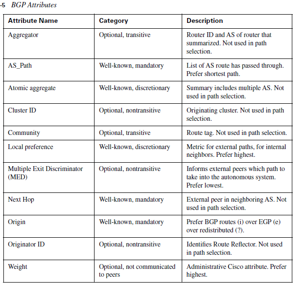
well known mandatory: everyone supports, must be in update message (next_hop, origin, as_path)
well known discretionary: everyone supports, might not be in update message (local pref, atomic aggregate)
Optional transitive: travel from router to router or from AS to AS
Optional non-transitive:  does not travel from router to router (Aggregator, MED)

Most  preferred: Ignore
In bgp table : * means valid  and > means best route

Two ways to get networks into BGP
-network commands
-redistribution

BGP synchronization:
Do not use or advertise a route learned via IBGP until the same route has been learned from the internal routing protocol.

BGP next-hop processing:
-for IBGP peers: do not change next hop address on advertised routes.
-for EBGP peers: change next hop address on advertised routes.

When we create neighbor relation within IBGP or Ebgp between loopback addresses we need to use update source loopback
when we create neighbor relation between ebgp routers having loopback address we need to use ebgp multihop since loopback address sees itself sees as one hop away.

When only BGP is configured on IBGP, do no synchronization on all routers in AS and do clear and reset the process(clear ip bgp *)

Issue: since with IBGP, next hop is not changed, internal router will not be able to reach ebgp router so solution is to redistribute external ebgp route to routers in internal AS or another solution is to set next hop- self  command  in border router.

Weight is cisco propriety and its local to the router. It is set on per neighbor basis.

To disable the neighbor
neighbor 10.1.1.2 shut

origin code: i iGP(entering with network command) or e EGP or? incomplete (redistribute routes into BGP)

local pref : advertised within AS
bgp default local-preference 100. Mainly used when we want to pass routes through that particular router.

policy_routing : the programming language of routing table.


L2 Trunking and Tunneling Notes

Ethernet:
802.1q tunneling  mainly used in  Core

Layer2 Security:
port security, PVLANS, VACLS, DHCP Snooping, etc.

Layer 2 QoS.
Classification, Marking, Policing, Queueing, etc

Ethernet Interface Types.
Layer 2 Switch ports
- Access  ie one vlan
interface f 0/1
switchport mode access
switchport access vlan 10

- Trunk == multiple VLANS

ISL is cisco propriety
All traffic encapsulated with ISL

802.1q
open standard
native vlan sent untagged.

DTP (dynamic trunking protocol)
Used to automatically negotiate what are trunk links supposed to be.
verified with ..
show interface trunk
show interface switchport
show spanning-tree [vlan | interface]

desirable mode == initiates trunking negotiation
auto mode = passively listen for trunking negotiation

Disabling DTP negotiation
Switch port non-negotiate
Switch port mode access
Switch port mode dot1q-tunnel

- Tunnel = transparent Layer 2 VPN

- Dynamic = DTP negotiation

Layer 3 Ports
- Switched Virtual Interface (SVI)
- Native Routed Interface


802.1q Tunneling
==================
1. Layer 2 VPN over switched ethernet network
Lightweight version of MPLS L2VPN
2. SP's PE adds additional 802.1q tag to all frames received from CE
called "metro tag" or "QinQ"
3. PE assigns all CE facing ports to the same VLAN
One vlan per customer in P network.

Configuration
-switchport mode dot1q-tunnel
tell switch to double tag frames
-switchport access vlan {vlan}
metro vlan assignment

Verification
-show dot1q-tunnel

Cannot be dynamically negotiated.

802.1q Tunneling Design Issues:
================================
Assumes L2 network end to end
- PE - P - PE links must all run layer 2 trunking
- Implies scalability issues.

Additional tags increase payload size
- 4 bytes per tag
- potential to exceed MTU of the transit path
- Ethernet doesn't support fragmentation

Loass of control plane signaling for CE devices
- CDP, VTP, STP etc dropped by PE.


Layer 2 Protocol tunneling
==========================
used to tunnel layer 2 control plane protocols between ports
-used with 802.1 q tunnel

Support for .. -cdp, vtp, stp, PAgP, LACP, and UDLD.

EtherChannel over 802.1q Tunnels
===================================
CE can suppport aggregation of CE-PE links
eg 2*GigE per customer site

EtherChannel must be point to point
- Implies one metro tag per PE-CE link

PE can tunnel negotiation as well

-l2protocol-tunnel point-to-point [lacp | pagp]

L3 Routing Notes

Layer 3 routing process of the Switches :
Switched virtual interfaces(SVI)
-interfaces vlan [1-4094]
-vlan must exist in the database first

Native routed interface
- no switchport
-same as ethernet interface on a router

Sw1# show ip route
Default gateway is not set
ICMP redirect cache is empty == means ip routing is not set in switch.
If gateway is not set, switch will try to do arp for all destination ips.

To turn on ip routing in switch
switch(config)# ip routing

Routing can be used over trunk interface. It is advisable to do so since it does not use STP and hence will not have convergence issues.

Layer 3 Routing (Contd)
Router on a Stick
-Layer 2 switch trunks traffic to external L3 router
-legacy version of SVI

Router usually does not support DTP and VTP
-switchport mode trunk
-switchport trunk allowed vlan

Router encapsulated ISL or 802.1q traffic using sub-interfaces
-encapsulation [isl | dot1q] {vlan} {native}

Native vlan must match
-Can be on the main interface or subinterface with native keyword.

Note: sub interface and vlan number need not to be matched. We are doing so just for clarity.

There will be only one native vlan on a trunk

Etherchannel Notes

Etherchannel
================
used to aggregate bandwidth of physical links
-same logic as PPP multilink

Consists of two parts
-port-channel interface
 ie logical interface representing the link bundle

-members interfaces
 physical links part of a link bundle

Channel can be any type of interface
 ie layer 2 access, trunk, tunnel or l3 routed.


Etherchannel Negotiation
==========================
channel-group [number] mode [mode]
Mode determines how negotiation occurs
- ON
 No negotiation

- Desirable & Auto (used in PAgP)
 Initiate of listen for PAgp

- Active and Passive (used in LACP)
  In active state  send LACP and in passive state listen for LACP
PAgp vs LACP is like ISL vs 802.1q also LACP is defined in 802.3ad

Ether channel Mode compatibility
===================================
On - On
Desirable - Desirable
Desirable - Auto
Active - Active
Active - Passive

Ether Channel Load Balancing
===========================
Load balancing between member interface based on..
-source mac
-dest mac
-source ip
-dst ip
-combinations of four

Modified with..
- port-channel load-balance

Layer 3 EtherChannel
=====================
Issue the no switchport command on members interface first
- order of operations issues

Ip address and other logical options go on the Port-channel interface

Ether Channel
===================
show etherchannel summary
L2 : show spanning-tree
L3 : show ip route


STP(Spanning Tree Protocol) Notes

How STP works
======================
Elect on root bridge
elect one root port per bridge
elect Designated ports

Root bridge act as ref point and path calculation happen based on it.

Switch with lowest bridge ID in network becomes Root Bridge

Bridge ID contains ..
- Bridge Priority
0 - 614440 in increments of 4096

- System ID extension
0- 4095

- Mac address

priority of 0 is most preferred for root bridge

Changing the root bridge election
==================================
Manually change BID priority
  spanning tree vlan [vlan] priority
  Lower is letter

Use root bridge macro
  spanning-tree vlan [vlan] root [primary | secondary]
  sets local priority based on current root bridge

Verification
  show spanning-tree vlan [vlan]
  show spanning-tree root

Note: bridges on the rest of the network will only use timer set in root bridge

default version of STP is PVSTP+

Root port opposite is always DP

Root and designated port election
-=====================================
DPs are downstream facing away from root bridge

Like root port election based on ..
-Lowest root path cost
-lowest BID
-lowest PortID

All other ports go into blocking mode
- receive BPDUs
- Discard all other traffic
- Cannot send traffic


Changing the Port's Role
================================
Modify the port's cost
 spanning- tree vlan cost
 bandwidth [bps]

Modify the bridge ID
 spanning-tree vlan [vlan] priority

Modify the Port ID
 spanning-tree vlan [vlan] port-prority

verification
- show spanning-tree interface [int] detail
- show spanning-tree vlan [vlan] detail

Why priority is always in increment of 4096?
When the extended system ID is used, it changes the number of bits available for the bridge priority value, so the increment for the bridge priority value changes from 1 to 4096. Therefore, bridge priority values can only be multiples of 4096.
Note that 2 raise to power 12 is 4096. Now if you occupy even a single bit ( out of the 4 bits) for the Bridge Priority,
It means 4096*2=8192 (multiple of 4096..)
The extended system ID value is added to the bridge priority value in the BID to identify the priority and VLAN of the BPDU frame.

Port ID = port priority + port no
default port priority is 128.

STP Timers
=============
Timers effect the transition between port states
  - set only on the root bridge

Hello
  - How often configuration BPDUs are sent
  - defaults to 2 sec

Max Age
  - How long to wait in blocking state without hearing BPDU
  - defaults to 20 sec

Forward Delay
  - How long to wait in each the listening and learning phases while building CAM table.
  - defaults to 15 sec


Note : In STP, CST and PVSTP only root bridge is allowed to generate BPDUs. BPDU start at root and forward towards leafs.
worst case convergence timer for STP is 50 sec
Timers are set in root bridge only:

Changing STP Timers
=====================
Configuration
 - spanning-tree vlan [vlan] hello-time
 - spanning-tree vlan [vlan] forward-time
 - spanning-tree vlan [vlan] max-age

Verification
 - show spanning-tree vlan [vlan]

 Advanced STP features
=======================
Portfast (direct from blocking to forwarding)
-edge ports shouldn't be subject to forward delay
- also effects TCN generation

UplinkFast
-Direct root port failure should reconverge immediately if Alternate port available

Backbone Fast
-Indirect failures should start recalculating immediately.

CAM age time == max-age time. when topology change notification happens

default CAM aging time is 300 sec

portfast is also called as edge port.

portfast interface will not generate the TCN and edge ports are not subject to forward delay. Also, CAM table does not flushed out and hence cuts down unknown unicast flooding on the network. when portfast is on it does not mean STP is disabled the switch is still sending and listening BPDU's and (their is a default defense protection mechanism and if interface receives BPDU's it put itself out of edge port or portfast status) ie if router or any end device need to run stp, we will enable stp on router ie end device and the switch interface which receives BPDU will put itself out of edge port.

So instead of configuring portfast on every interface we have command which will enable portfast on all interfaces of switch ie spanning-tree portfast default this is equivalent as # int range fa0/1 - 24 , g0/1 -2 + spanning tree portfast and interfaces will automatically figure it out which one should run portfast and which one should not based on built on mechanism.

For trunk link portfast will not be on by default. if trunk links goes down and comes up it's not going to create TCN

UplinkFast
=========
Spanning-tree uplinkfast == should be configure in single switch

Backbonefast
============
Spanning-tree backbonefast = > should be configure on all switches
These features are used for fast convergence. We need not to wait for max age time.
 Still with this feature convergence time is around 30 sec which is not enough.

STP BPDU Filter
============
BPDU Filter:
-To drop STP packet as they come into the interface or go out of the interface ie filter BPDUs in and out
- Can be configured per interface basis or globally . If configured at interface, the STP is disabled at interface and if configured globally stp is disabled on all interfaces. Typically used at access layer. This is mainly used to avoid L2 attacks.
Spanning-tree bpdufilter enable. Its like a passive interface. A disadvantage is when a router connected to this switch want to run STP, router will send BPDUs but switch will not receive BPDUs.

BPDU Guard
-If BPDU is received shut port down. Link is put in err-disable state.it will not come out of it until err-disable recovery timeout or manually brought up.

Root Guard
-if superior BPDU is received shut port down.

Loop Guard & UDLD
-Prevent unidirectional links
Typically in the case of fiber network where send channel might be working but receiving channel might not be working. One physical link for sending traffic and other physical links for receiving traffic. It is possible to have one working and other break. In STP if we are able to send BPDUS but not able to receive BPDUs then max age time out will happen and port will move from blocking to forwarding since it will not rx BPDUs from other end and it will put itself in DP and it might happen both switches elect DP ports  and both interface will be in forwarding state. This is the violation of STP but STP will not detect this since it is a L1 issue. Solution is loop guard and unidirectional link detection

Multiple Spanning-Tree Protocol
===================
IEEE (802.1s) response to PVST/PVST+
-supports rapid STP (802.w)

Instances are separate from VLANs
-PVST+ uses one instance per VLAN
-MST uses definable instances

Highly scalable
-Switches with same instances, configuration revision number, and name form a “region”
-Different regions see each other as virtual bridges.

Disadvantage of  STP is more overload.  If there are multiple vlans associated with same physical interface we need to create separate instance of STP for all vlans.

MST Path Selection
======================
Same election process as CST/PVST
Root Bridge
-lowest BID

Root port
-lowest cost
-lowest upstream BID
-lowest portID

Changing MST Root Bridge Election
==========================
Manually change BID priority
-spanning-tree mst [instance] priority
-lower is better

Use root bridge macro
-spanning-tree mst [instance] root [primary | secondary]
-sets local priority based on current Root Bridge

Verification
-show spanning-tree mst [instance]
-show spanning-tree root

Note: with RSTP we need not to configure uplinkfast and backbonefast. Those are enabled by default.
Typically we want root bridge somewhere in the core.
In case of MST sys id comes from Instance number of MST.
Rstp is automatically enabled when we turn on MST.
MST0 instance is used for inter region operability. MST interact with PVSTP through MST instance 0 ie MST0
Role of VTP in MST is to advertise the instance between the neighbors.

Changing an MST Port’s Role
=========================
Modify the port’s cost
-          Spanning-tree mst  [instance ] cost
-          Bandwidth [bps]

Modify the Bridge ID
-          Spanning-tree mst  [instance] priority

Modify the port ID
-spanning-tree mst  [instance] port-priority

Verification
-show spanning-tree interface [init] detail
-show spanning-tree mst [instance] detail

Rapid Spanning-tree protocol
==========================
Rapid convergence based on sync process
Enabled through..
-spanning-tree mode mst
-spanning-tree mode rapid-pvst

Sync process only occurs on point-to-point non-edge ports
-implies link-type must be accurate
-spanning-tree link-type [point-to-point|shared]
-spanning-tree portfast

Root -----à downstream
Upstream--à Root

If links are not point to point ie full duplex then proposal process will not happen. Especially in the case when link is connected to hub.
In that case we have to use legacy STP.

So requirement is linked between the switches are point to point and non-edge ports and all other interfaces connected to end host should be defined as edge port as defined portfast command  in STP.

Portfast in STP is equivalent to edge port in rstp.